Shock Tuning Primer - How a shock works
Part 2 (Part 1)
By Marcus McBain
All information, copyright 2012 Marcus McBain/RPSRaceTeam.com
The nitrogen chamber
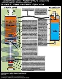
Although the nitrogen chamber is the most critical technology function, it has not been discussed yet. It is time to shed some light on this subject. The nitrogen chamber is a dynamic component to the overall performance of the shock. What the nitrogen chamber provides for the shock is the ability to “move” at a rate that is controlled by the low speed compression and rebound adjusters as well as the external high speed adjuster.
With all the various movements required by the shock, the Nitrogen chamber is the key to allowing all of this happening without adverse effects to any other action(s) within the shock. The Nitrogen chamber is located in the reservoir. The cap to the reservoir has either a Schrader valve OR an access point for a needle to fill the chamber with Nitrogen (various manufacturers use 150lbs. – 300lbs). A floating piston separates the Nitrogen chamber from the Oil Chamber. This floating piston moves as pressure from the Shock Shaft compressing into the shock body displaces volume. The Nitrogen chamber compresses initially and as pressure builds up will smoothly prevent the floating piston from moving too much. After the force causing the floating piston to move is over, the pressure within the Nitrogen chamber pushes the floating piston back to the original position, which in turn (with the help of the spring) causes the shock to extend back out to its “at rest” position.
The Nitrogen chamber works so well at addressing low speed movement, that the design was widely introduced into forks around 2002-2003. Although forks have a much different set of challenges to meet in relation to the suspension duties, Nitrogen chambers in forks (Gas Forks), work very well and do provide great performance for top riders.
How the damping circuits work together
So far we a have discussed a lot of specific individual component theory, now it is time to “put it all together”. We will discuss compression and rebound separately, but in detail respectively. Each description is a complete action and demonstrates how the logical circuits all work together.
Before we go over the example, it is important to understand that although the compression and rebound have low and high speed circuits they all work together respectively. The external high speed compression additionally is a transitional component of the compression circuit that has characteristic effects similar to the low speed circuit, BUT at the same time affects the shock when the shock shaft is moving faster than the low speed circuit was designed to handle. The circuits are as follows:
-
Low speed compression circuit – The easiest one to identify and understand. It is an oil passageway (orifice) that is controlled by the external low speed compression adjuster (metering needle). Turning in the low speed compression adjuster allows less oil to move through the orifice and provides more damping (resistance). Turning the low speed compression adjuster allows more oil to move through and provides more movement.
-
External high speed compression adjuster – This is a transitional damping circuit that helps the shock progress from the low speed compression circuit to the opening of the piston compression stack. The damping range it provides prevents a significant damping/velocity gap between the low speed compression circuit and when the internal compression shim stack opens. NOTE: In most cases, the Low speed compression circuit and externally adjustable high speed compression circuit are adjacent to each other or share the same “exit port” for oil flow.
-
Internal high speed compression circuit (internal piston compression shim stack) – Both the compression and rebound shim stacks are the “lowest common denominator” for the respective duties. The reason for is this is that internal high speed stack will open marginally and for short durations before fully opening when varying forces are introduced into the shock. You want the internal high speed compression stacks to be able to open “a bit” on the marginal bumps, BUT you don’t want it to “fly open” every time (which happens a lot on “standard build” shocks with more aggressive riders).
-
Low speed rebound circuit – This is a simple orifice that has an adjustable metering rod controlled by the external rebound adjuster. As the shock shaft extends back out, oil from the bottom side of the piston must displace to the top side otherwise the piston would be “hydro-locked”. The low speed rebound orifice is located below the piston on the shock shaft and has a relief/exit port on the top side of the shock shaft (above the piston). Several manufacturers put a restriction device in the shock shaft so that there is not excessive bleed on the compression stroke (reversing through the low speed rebound circuit).
-
Internal high speed rebound circuit (internal piston compression shim stack) – This is the most important damping circuit in the shock. The primary reason is that the performance of this damping circuit affects the ability for the rear tire to maintain traction on the exit of a turn. If the circuit is “weak” (soft shim stack), the rear suspension will “wallow” (lazy up and down gyration of the rear suspension). If it is too stiff, then tire will be taxed and abruptly “step out”. This is a difficult circuit to build perfectly as the rebound stack has to consistently open up partially or briefly for maximum performance.
-
The main culprit that causes the difficulty in “building this right” is that at the point of the shock being compressed more than halfway is that the spring is usually providing several hundred pounds or more of force “up” AND the nitrogen chamber is also adding significant pressure as it is trying to resume its “at rest position”. The tendency of the rebound circuit is to initially move really fast as it starts the rebound stroke, BUT once that happens the velocity generated up can make the stack “fly open” and stay open until the shock has recovered to the “at rest” position.
-
When the rebound shim stack is properly built it allows the initial movement needed for the shock to recover, BUT still close as needed so that the shock can smoothly resume an “at rest” (topped out) position.
Now that the specific functions of the circuit(s) have been covered, let’s examine what actually happens in the compression and rebound strokes. The following examples provided take you through the low and high speed actions during the compression and rebound stroke.
-
In this example, the rider is exiting a turn. As the rider begins to set the throttle to accelerate out of the turn, the low speed circuit begins to be utilized as the throttle is applied harder and the rear tire tracks over bumps, then the high speed circuit(s) are opened. The actions can occur over a 3 second period or less than ¼ of a second depending on the bumps, speed, and action of the rider. Regardless, all actions happen in the order presented.
-
Under initial compression of the rear, the floating piston will recess in the remote reservoir and allow the rear to squat. Oil flow is controlled by the low speed adjustment. Pressure will begin to build in the Nitrogen chamber.
-
As the Nitrogen chamber pressure increases, the floating piston stops moving. As oil from the oil chamber continues to be forced into the remote reservoir, pressure is being generated. At this time, the external high speed compression circuit opens the shim stack within the remote reservoir and more pressure is put on the Nitrogen chamber causing it to continue to move.
-
With the Nitrogen chamber increasing in pressure again and as the shock shaft is continuing to create force from a harsh bump, the internal high speed compression stack opens (located in the remote reservoir). Although this allows quicker movement, the volume displaced by the shock shaft as it compresses in the shock body increases pressure and resistance which slows the shock shaft down as the forces causing the shock to compress subside.
-
-
The rebound action is a simple, but critical operation. We will continue the previous example, BUT the rider is now completing the exit of the turn.
-
As the rider passes the peak torque curve of the engine, force on the rear suspension begins to lessen. With the shock heavily compressed, the shock spring and the Nitrogen chamber is putting tremendous pressure on the shock shaft and it begins to extend back out. The initial part of this action sees oil enter into the low speed rebound oil port/orifice below the piston. This allows oil to be metered as it travels through the (hollow) shock shaft through the topside (of the shock shaft).
-
-
Seamlessly the rebound shim stack begins (if all is working right) to open slightly as the capacity of the low speed circuit is exceeded and force continues to push on the shock shaft. Next, as the engine torque and hp curves fall off, then much of the “down force” that was keeping the rear suspension from rising too fast is gone. With over 500lbs of force pushing up the shock shaft, the internal rebound stack now opens fully.
-
IF the shock is built well, then the internal rebound shim stack will open just briefly and let the low speed circuit resume the damping duty to return the shock to its topped-out position.
-
IF the shock is built poorly, then the internal rebound shim stack will open quickly and for an extended period of time…which the rider will notice that the rear tire will start to “step out”.
Those are the actions of the shock in a nutshell. 10 illustrations are provided separate from this primer to allow you to intimately view each of these actions. A big key to performance in the shock is that the shim stack(s) should open in two manners. (1) When marginal pressure is applied, it should not “blow open”, it needs to open for a short amount of time to allow the shock shaft to achieve velocity. At the same time, when it does blow open out of necessity, it needs to shut quickly.
Key build and maintenance items
An aftermarket shock is a great performance enhancement for your motorcycle, but there are many maintenance items that will continue to provide you a “new shock” performance level. This isn’t a thought or slogan, but a statement from facts. The RPSRaceTeam.com GSXR-750 shock enters its SIXTH straight season of use in 2012. During that time, RPS has replaced every part that is affected by wear at least twice. During that time, the shock has started over 280 races with over 150 podiums and nearly 100 wins captured in that time frame. Here are some vital maintenance items and build techniques that have been observed as critical to long term performance and reliability.
-
Change the oil every 5-20 hours – Oil is cheap relative to the cost of the shock. Keep fresh oil in the shock to prevent wear that will be detrimental if you plan on keeping/using your shock for several years. In climates where you are racing with ambient temperatures over 105 degrees Fahrenheit, the 5 hour time frame applies. In more moderate climates 20 hours is very reasonable. RPSRaceteam.com routinely races at venues with over 105 degree temperatures and track/asphalt temperatures over 140 degrees. We have found that the excessive heat is hard on the oil.
-
Use 2.5 weight oil (or relative lighter oil) – Most shocks come with recommendations for 5 weight oil. Using a 2.5 weight oil allows more precise damping actions AND provides fade free performance.
-
Remove, inspect, and replace worn internal high speed shims on the piston every 40 sprint races (15-20 sprint races (about 250 laps) for the fastest riders) – Yep, using a shock hard also wears out the shims. No kidding. When you pull the shims off, if you see “bend marks” on the shim(s). Replace them.
-
Remove, inspect, and replace all seals every 30 hours of use.
-
Remove, inspect, and replace the piston band every 30 hours of use.
-
Remove, inspect, and inspect the bearing seals/bushing every 30 hours of use.
-
Install Torrington bearings on the spring seats to prevent “coil bind” – Believe it or not, your shock spring was not designed to compress “straight up and down”. It actually wants to “bow out” to one side of the shock. Installing Torrington bearings allows the shock spring to rotate and flex with minimal “stiction”.
All of the recommended service levels are very short in schedule length. They are provided based on “hard use” under extreme conditions. This is the schedule that RPSRaceTeam.com has used for several years with very good results.
How to pick a vendor
Picking a vendor is a difficult proposition. As you become more knowledgeable about suspension, you quickly realize that many of the vendors are questionable at best. Although common sense dictates that you should choose the vendor that gets the most “public love”. RPSRaceTeam.com has found that many vendors that have this type of following are just as likely to be incompetent as credible. Just because a vendor is giving great price breaks on hard parts (which people seem to think is the “value” in suspension), doesn’t qualify them for anything other than a parts store. A quality suspension person is not going to discount their products because they know the amount of service required even under the best of circumstances.
If you are going to be “at the track” mostly when you ride your motorcycle, choose a trackside vendor that WORKS AT THE TRACK. Specifically, make sure they can re-valve and service components at the track. If they don’t do that, it is the #1 sign they don’t really understand their job/work.
Also, make sure if you are picking the vendor based on “a few fast guys” that use them…MAKE SURE THEY ARE THE ONES ACTUALLY installing the product. RPSRaceTeam.com has consistently seen over the years shops/vendors sponsoring riders with suspension products they don’t actually build.
The big boned (yes, fat) guy does have a leg up on the competition. One of the advantages of being over 200lbs, you can actually make the suspension go through the stroke better when pushing on the bike. NO, your suspension guy doesn’t have to be over 200lbs, but if you watch him push on the bike and it only moves an inch or two…he can’t possibly know what is going on in the shock or suspension.
-
I have in the past (when I was under 200lbs.) actually setup bikes by jumping on top of them while idling through the pits. It looks kinda funny, but it gets the suspension to move through the stroke and provides a great way to feel what the suspension is doing.
-
Being able to bounce on the bike doesn’t mean that the vendor is qualified. 90% of being a good suspension tuner requires that they (the tuner) listen to rider, AND THEN understand what the bike is actually doing. Most riders don’t properly describe what is going on and it is up to the tuner to take the rider feedback and combine that with what they feel is going on…THEN make the proper correction.
-
No, you don’t have to necessarily have to be able to “bounce” on a bike with the weight of a gorilla. It just makes the job easier.
Talk to your suspension vendor and ask them, “what kind of service they provide after the sale, what kind of work is required to make the suspension work optimally, and what level of service do they provide for maintaining the suspension?” Most quality vendors will have a preset strategy and schedule for when you ask/purchase. Bike setup is mostly contingent on your performance and feedback and they should let you know that. In the same breath they should also tell you of their support program(s) at the track to help. It may be as simple as calling the vendor and they will work with you over the phone OR they may be trackside. If a shop doesn’t have an organized approached, most likely they don’t expect you to come back to them. That is not a good sign.
Lastly, you are the most important part of getting your motorcycle’s suspension to work properly. If you are showing up late to practice, not maintaining the motorcycle, and using ratty ass old tires during practice, don’t be surprised that your motorcycle doesn’t work as well as your expectations or hopes. If you want to get faster, then you need practice tires with actual life left in them.
Emerging technologies and tuning strategies
As we conclude this introduction to “how a shock” works discussion, there are some emerging technologies and trends that many riders ask about. The two biggest items over the last few years have been smaller diameter pistons and changing of valving strategy.
If you look at the motorcycles at the racetrack you see two primary sized pistons/shock bodies (36mm +/- and 46mm +/-). The 46mm piston diameter/shock is the “old standard” and works well. The strategy with the smaller diameter pistons is that they provide less “stiction” and the smaller shock body allows the pressures/circuits to respond quicker. It is a lot like the technology discussion of 20mm fork cartridges vs. 25mm/30mm cartridges. Yes, both have technical features that theoretically work better than the other, but at the end of the day, the rider has to make that decision of what works best.
Valving strategy is always changing. As you witnessed on the dynosheet and in the discussions on rebound damping, RPSRaceTeam.com puts an emphasis on rebound damping. What several manufacturers are doing now is beefing up the strength of the compression stack and making the rebound stacks softer. The reasons for this (among others) are (1) if the shock doesn’t go down as fast, then it won’t be constantly “loaded up” on the bottom of the stroke, (2) some of the newer tires have a very flexible casing and work better with stiffer damping on the compression stroke, and (3) with traction control being so prevalent, it is easier to setup a bike that does break traction with more action so that the traction control can more accurately control the spin of the rear tire.
Thank you for using our “how a shock works” guide. There are 10 distinct technical drawings provided to accompany this presentation on www.RPSRaceTeam.com. If you found this article of value to you, PLEASE donate to the RPSRaceTeam.com “Syndicate” accessible on the link below. Readers that donate over 25.00 will receive a high resolution PDF of this article and the 10 technical drawings provided for their own personal use.

RPSRaceTeam.com "How a Shock Works" Copyright 2012 Marcus McBain/RPSRaceTeam.com

RPSRaceTeam.com "How a Shock Works" Copyright 2012 Marcus McBain/RPSRaceTeam.com

RPSRaceTeam.com "How a Shock Works" Copyright 2012 Marcus McBain/RPSRaceTeam.com

RPSRaceTeam.com "How a Shock Works" Copyright 2012 Marcus McBain/RPSRaceTeam.com
Downloadable Illustrations
These PDF illustrations are provided for a complete viewing experience.